|
|
|
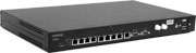
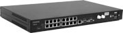
Fiber Optic Multiplexors FMUX/S (with ring support)
Specifications
Optical Transceiver Parameters
Documentation
|
Features
|
Multiplexors of the FMUX family are capable to transmit up to 4, 8 or 16 E1 channels over the fiber optic link. All channels have independent sync signals with their own frequencies.
There are budget FMUX/M versions of E1 multiplexers. These versions are fully compatible by fiber optic and ring support capabilities with FMUX/S models described it this page.
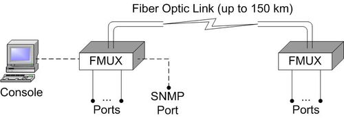
Typical point-to-point application configuration is shown below:
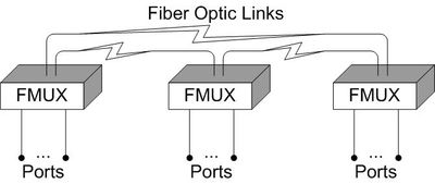
The ring application configuration is also supported. Compatible devices other than FMUXes may be also included in the ring. The minimum ring configuration example consisting of 3 devices is shown below:
There are versions for transmission of one or two additional digital port channels: Ethernet (10/100Base-T) and/or multistandard (V.35/RS-530/RS-232/X.21).
FMUX has LEDs for channels ready state, optic transceiver operability, loopbacks enable state and test mode indication.
Internal loopbacks and integral BER tester operation are controllable by the console port located on front panel.
BER tester meters bit error rate in optic link using permanent or pseudo random code in compliance with the ITU-T O.151 Recommendation (test sequence length equals to 223-1=8388607 bits).
Remote device management is available by remote login feature. Service data exchange is supported by additional service channel using same optic link (available in point-to-point configuration only).
Device state can be monitored by SNMP using dedicated Ethernet 10Base-T port ("-SNMP" option must be ordered).
Alarm indication relay with "dry contacts" interface in compliance with the ITU-T G.742 Recommendation, paragraph 10, is supplied.
The firmware of the device can be updated by user.
Ordering:
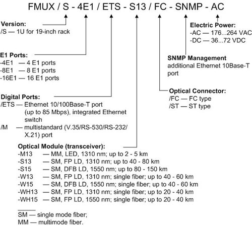
Currently available models are listed in Prices. Please, contact technical support if you are unsure which model to choose.
| E1 Interface (2048 kbit/s) | |
|---|---|
| Connector Type | RJ-48 (female 8 pins) |
| Line Code | HDB3 |
| Framing | Transparent; both framed and unframed modes supported |
| Error Detection | Bipolar Violation |
| Line Impedance | 120 Ohm (Twisted Pair) |
| Receive Signal Attenuation Range | From 0 to -12 dB |
| Jitter Attenuator | In transmit path |
| Overvoltage Protection | TVS |
| Overcurrent Protection | Fuse |
| Multistandard Interface | |
| Data Rate | from 64 kbps up to 8192 kbps |
| Clock Signals Supported | TXC, RXC, ETC, ERC |
| Modem Control Signals | DTR, DSR, CTS, RTS, CD |
| Connector Type | HDB44 (female) |
| Ethernet 10/100Base-T Interface | |
| Interface Type | IEEE 802.3 10BASE-T/100BASE-T (100BASE-TX) |
| Connector Type | RJ-45 (female) |
| Data Transfer Rate | up to 93,5 Mbps |
| Mode | 100 Mbps Full-duplex, 100 Mbps Half-duplex, 10 Mbps Full-duplex, 10 Mbps Half-duplex, or Autonegotiation |
| Maximum packet size | 1552 bytes, including MAC header; VLAN supported |
| Quality of Service | 2 priority levels |
| LAN switch | Integrated, has 2 (for "4E1" model) or 4 (for "8E1" and "16E1" models) Ethernet ports |
| Alarm Interface | |
| Connector Type | DB-9 (male) |
| Relay Contact Current | Up to 600 mA |
| Relay Contact Voltage | Up to 110 VDC; up to 125 VAC |
| Console interface | |
| Connector Type | RS-232 DCE, DB-9 (female) |
| Protocol | Asynchronous, 9600 bit/s, 8 bit/symbol, 1 stop bit, no parity |
| Modem Control Signals | DTR, DSR, CTS, RTS, CD |
| Diagnoctic modes | |
| Loopbacks | Local, Remote |
| BER Tester | Built-in |
| Control | Via console RS-232 port |
| Physical | |
| Box | 1U rack mount for 19-inch cabinet |
| Dimensions | 444 mm x 262 mm x 44 mm |
| Weight | 3400 g |
| Power source | |
| AC power source | 176-264 V, 50 Hz |
| DC power source | 36-72 V |
| Power consumption | 20 VA Max |
| Environment | |
| Range of working temperatures | 0° to +50°С |
| Range of storing temperatures | -40° to +85°С |
| Humidity | 0 to 80 %, non-condensing |

![]() Installation and Operating Manual (in Russian)
Installation and Operating Manual (in Russian)
![]() MIB-files for SNMP-management
MIB-files for SNMP-management
Return to Fiber Optic Modems and Multiplexors or Digital Communication Equipment
Copyright © 1996-2026 Cronyx