|
|
|
Adapter Tau/E1
Discontinued, recommended replacement is: TAU-PCI/2E1
 |
Features:
|
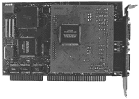
 The Tau/E1 is an adapter board for IBM PC and compatible computers with ISA bus.
It includes two E1 interfaces operating at distances up to 1.5 km and one
digital interface for a standby link. The adapter architecture is similar to
the E1-XL dual modem.
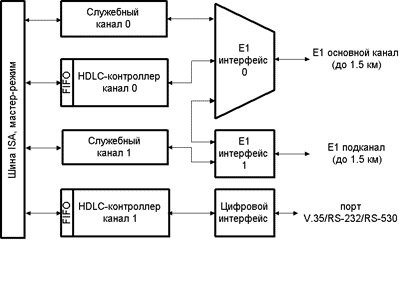
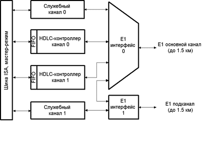
Tau/E1 can be configured by software for three modes of operation: (see Block Diagram below).
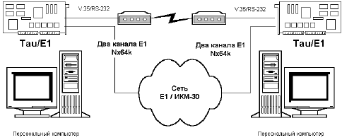
The Cronyx-Tau software allows to join several physical synchronous communication channels into one logical channel. For example, two channels with data rate 1984 kbps, joined together, will create the logical channel with the overall throughput of 3968 kbps.


Configuration A: Dual E1 accsess unit. E1 Link 0 and E1 Link 1 operate independently and have identical data pathes to the PC memory. Data transfer rate is determined by the number of timeslots used.

Configuration B: Integrating multiplexer with one data channel and E1 sub-link. The timeslots of main link (E1 Link 0) are assigned to data channel and E1 sub-link. The data channel to/from PC memory is supported by HDLC Controller 0. E1 sub-link (E1 Link 1) translates user-defined timeslots to the remote node. This configuration allows to split the main link data between several chained Tau/E1 nodes (up to 30) with the distance between nodes of up to 1.5 km. The Digital Interface and HDLC-Controller 1 create independent sync/async channel operating at data rates up to 4 Mbps.

Configuration C: Integrating multiplexer with two data channels and E1 sub-link. The timeslots of main link (E1 Link 0) are assigned to two data channels and E1 sub-link. Two data channels to/from PC memory are supported by HDLC Controllers 0 and 1. E1 sub-link (E1 Link 1) translates remaining timeslots to the remote node. This configuration allows to split the main link data between several chained Tau/E1 nodes (up to 15) with the distance between nodes of up to 1.5 km. For this configuration the Digital Interface is disconnected.
| PC Bus Interface | |
|---|---|
| Bus Type | ISA, 16 bit |
| I/O Base Address | 200h - 3e0h, Jumper Selectable |
| I/O Address Space | 32 Bytes |
| Interrupts | IRQ 3, 5, 7, 10, 11, 12, 15, Software Selectable |
| DMA Channels | DMA 5, 6, 7, Software Selectable |
| DMA Transfers | Master Mode, Word Bursts |
| Addressable Memory | 16 Mbytes |
| Serial Interface | |
| Data Transfer Rate per direction for each channel simultaneous operation | 4 Mbps |
| Bit Rate Generator | Independent per channel |
| Synchronous Protocol | HDLC |
| Asynchronous Transfer | 5-8 Bits/Character, 1/1.5/2 Stop Bits |
| Sync Mode Error Detection | Cyclic Redundancy Check CRC-16, CRC-CCITT |
| Async Mode Error Detection | Parity bit |
| Clock Options | TXCIN, RXCIN, TXCOUT or DPLL, Software selectable per channel |
| Modem Control Signals | DTR, DSR, CTS, RTS, CD |
| E1 Interfaces | |
| Data Transfer Rate | up to 1984 kbps (Nx64 kbps), Software selectable per channel |
| Line Code | AMI or HDB3, Software selectable per channel |
| Line Impedance | 120 Ohm (Twisted Pair) or 75 Ohm (Coax Cable), Jumpers selectable per channel |
| Receive Signal Attenuation Range | from 0 to 12 dB or to 30 dB, software selectable (up to 1.5 km of 22 AWG twisted-pair cable) |
| Jitter Attenuator | 128 bits depth, in the receive path |
| Frame Structure | per G.704 |
| Multiframes | CRC4, CAS |
| Frequency Offsets Adjustment | Controlled Frame Slip |
| Board Size | Height: 100 mm, Width: 167 mm |
| Operating Systems Supported | FreeBSD 4.x, 5.x, 6.x, Linux (FreeBSD 7.x is not supported) |
| Protocols Supported | PPP, Cisco/HDLC, Frame Relay |
![]() User's Manual in Russian
User's Manual in Russian
![]() Driver Development Kit Manual in Russian
Driver Development Kit Manual in Russian
![]() V.35 cable scheme
V.35 cable scheme
![]() RS-232 cable scheme
RS-232 cable scheme
![]() Справочник по интерфейсным кабелям Cronyx.
Справочник по интерфейсным кабелям Cronyx.
Return to WAN Adapters or Digital Communication Equipment
Copyright © 1996-2026 Cronyx
